
Ship air conditioning system
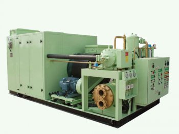 Ship’s air-conditioning and refrigeration system facilitates lowering room-temperature and in maintaining perishable food products and refrigerated cargo at desirable temperature.
As discussed within our article about concepts of refrigeration plant – Construction and Working of Ships Refrigeration plant on boats, the reefer and air conditioning methods tend to be put in to take care of fluctuating loads i.e. they have been accountable for maintaining low-temperature of a number of spaces or cargo keeps as well.
The efficiency associated with refer plant hinges on its ability to maintain different rooms or keeps at various temperature.
Understanding Capacity Control?
Capacity control of a refrigeration plant can be defined as a system which manages the production of plant as per force in demand. Whilst the load (temperature) of one room is accomplished, you will have no more need of refrigerant for cooling. Therefore, the solenoid valve providing refrigerant to that room will shut. This functionality is named capacity control.
 The refrigeration compressor is made of different products working in synchronous to deal with the load. Because the load decreases, the ability control system cut off one or more products (depending upon force) and preserves the efficiency regarding the plant by decreasing stresses on different parts.
Components and dealing of Capacity control system
1. Compressor lube oil pump offer
2. Capacity control valve
3. Capability control regulating valve
4. Un-loader installation
The compressor lubricant oil pump materials oil to any or all the bearings and one connection is provided into capacity control valve.
The capacity control device will get questionable oil from compressor lubricant oil supply pump. This valve has actually a few grooves bored into its periphery and connected to the un-loader procedure various units.
a springtime piston is offered which manages the spreading of high pressure oil supply into the bore chamber. The spring piston is pushed by the oil supplied through an orifice which pushes the piston and aligns the un-loader holes, providing ruthless oil toward un-loader product.
The un-loader installation includes a un-loader piston held by a spring. The un-loader piston is linked to a rotating cam band having raising pins attached to th suction device. The lifting pins constantly behave from the suction device in other words. un-loading the system at end problem.
Whenever bores on control valve aligns using un loader bores, oil will pass and push the un-loader piston rotating the cam and releasing the un loader pins from suction valve.
The ability control regulating device is accountable to regulate the pressure (opening and closing of capacity control valve ports with un-loader harbors). Its one end is connected to the crankcase as well as other end to capability control valve.
Share this article
Related Posts


Latest Posts


